
Handling PDF files for non-printing processes and embellishment.
One of the topics we hear a lot about at Ultimate is how to create and process PDF files that contain elements for finishing and embellishment. There is quite a lot of confusion out there, so the aim of this blog article is to review the options you have when working with these kind of PDF files and to point out some of the possible pitfalls.
Color Separations
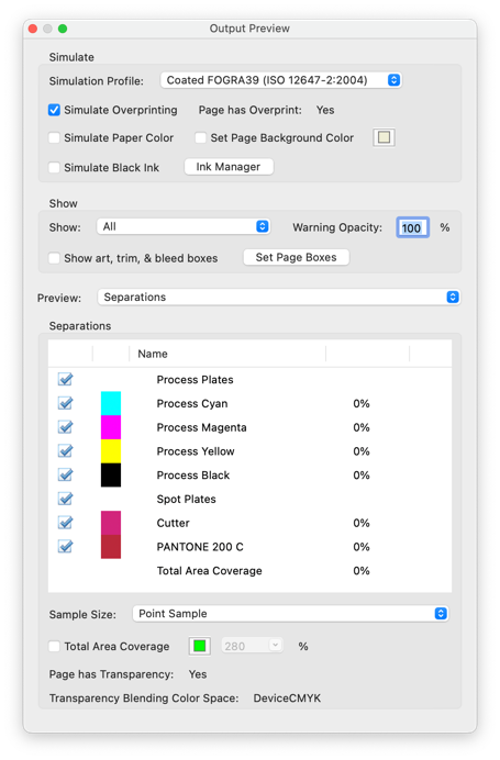
This is a production process most prepress people are familiar with. During the design process certain colors are defined. These are either defined as a colorant mix within a color space like RGB or CMYK, or as a named separation such as a Pantone color or a name for a production process such as ‘varnish’ or ‘cutter.’ On output each colorant generates a ‘separate’ film, printing plate, impression, or rendered image.
 With current production techniques, the PDF file for output is delivered to the output rip or DFE as a composite PDF file, so the color separation is done within the output Rip just prior to imaging. The fact the PDF is still a composite file until the last minute allows the opportunity to make last minute decisions and changes. This is a significant improvement from the days when files needed to be pre-separated much earlier in the production process, normally just before imposition.
Color separations are based on the name of the colorant. This can cause issues in some output processes when merging, imposing, or nesting PDF files as separation names that are meant to be the same can slightly differ which can lead to excess multiple separations when the intention was one.
To ensure that excess separations are not generated, some color mapping, color conversion or renaming of separations might be necessary. Even something like a Pantone color can generate more separations than necessary if colors are taken from different Pantone libraries. It is not unusual to see a mix of ‘C’ and ‘U’ suffixes being used for the same spot color in a PDF file, indicating the PDF has colors which have been selected from both the Coated and Uncoated Pantone libraries.
Many digital finishing devices require a separate separated one colorant PDF or will work with a composite PDF if the separations are named to their requirements. From a workflow perspective it is best practice to manage all color mapping and renaming prior to imposition, nesting or output.
Ultimate Impostrip® and color separations
If your workflow does require you split out single named separations for additional processes such as cutting or varnishing, you will be pleased to know this functionality is available in Impostrip, it was added last year to Ultimate Impostrip® 2022.2.
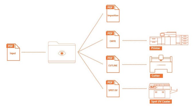
You can define the named separations to be split away as a new file, and a destination hot folder, which of course could be the input folder of the device. The resulting separations are actual object-based PDF files, not images. So, any vector shapes will be kept and produce the highest possible output quality at the resolution of the device.
The process is of course completely automated, so once configured, it just works.
Layers vs OCG’s
‘Layers’ were introduced into PDF with PDF version 1.5 in 2003, and they are commonplace now in production PDF files for many verticals like packaging, labels and large format.
It’s worth explaining at this point however that ‘layers’ in Adobe Illustrator and other design applications are quite different to layers in the PDF specification and therefore PDF tools like Adobe Acrobat. Layers in PDF are not really layers. To give them their correct term they are ‘Optional Content Groups’ or ‘OCG’s’.
A layer in a design application has object(s) ‘placed’ on the layer. Layers can be locked, allowing you to work only on objects on certain layer(s) without affecting others. The position of the layer in the object stack directly effects the position of the objects placed on it. Layers (and therefore the objects on them) can be moved above and below other layers effecting the visual representation of the design.
Layers in PDF and Acrobat should not really be called layers, as they perform very differently to the layers in design applications. Their correct name is ‘Optional Content Groups’ or OCG’s. As the name suggests they were designed with the purpose of making content in a PDF file optional, (OCG on, OCG off). A typical example of their use being a book with multiple language versions. Rather than split the PDF into multiple PDF files for each language, you can have one PDF file with all the languages included in it. The elements for each language are assigned to an OCG, and when each language is output the OCG associated with it is on, but the rest of the language OCG’s are off. This makes the file much easier to work with at the design stage and to proof and manage.
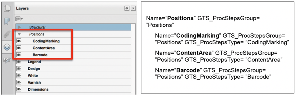
Important to understand is that in PDF objects are not ‘placed’ on OCG’s, they are assigned or associated with an OCG or multiple OCG’s. It is perfectly possible to have an object(s) in a PDF that are assigned to multiple OCG’s.
If an OCG is on, the object(s) assigned to it are visible and will be output. If the OCG is off, then objects associated with it are not visible and will not be output. The ‘off’ layers will be ignored by the output rip or DFE. I should mention here that this statement comes with the warning that your rip or DFE must correctly handling OCG’s. I’ve heard many stories of hidden layers suddenly appearing on output because the output rip cannot support them or is not correctly configured.
OCG’s have absolutely no bearing on the object stack. You could have an object at the front, an object at the back, and an object in the middle of the object stack, and they can all be assigned to the same OCG. There is no concept of moving OCG’s up and down and changing their order.
There are however options available regarding OCG’s that allow you to define settings like the initial view when a file is opened, and settings regarding visibility printing, and exporting.
The former can be useful if you are sending a PDF to a customer as a proof. You may decide for instance that when a customer opens the PDF you want to hide all the layers relating to finishing and only show them the actual printing inks. Defining the initial view allows you to do this, but the viewer keeps the ability to toggle them on and off if he wishes to.
Processing Steps – ISO 19593-1
Today OCG’s are commonly used for non-printing content such as cutter guides, die lines, and structural information etc, but this is not without its issues if you are trying to automate your workflows and maximize efficiency.
One of the main problems of working with OCG’s is that just like separations, standards just do not exist for their use and their naming conventions. If you are working with incoming customer files, you may receive files with OCG’s that should be the same but are named very differently such as ‘Dyeline, ‘Cutter’, and ‘Coupe’ for example. This is not a great situation if you are trying to automate your production processes as these will need to be resolved to a single OCG using the standard practices within your company.
To resolve this issue the Ghent Workgroup (gwg.org) defined a method of working with OCG’s that has now become an official ISO international standard. ISO 19593-1. In brief, what this standard does, is use metadata attached to an OCG to define the purpose of it. The name of the OCG is irrelevant. The metadata is not visible to a user, but it can be read and recognised by other compliant software.
This means that if your compliant workflow, software, Rip or DFE receives such a PDF file, it can identify the purpose of the OCG’s within the PDF from this metadata and process the component parts accordingly. This means that PDF files do not have to be broken down into multiple PDF files for different processes. The same PDF file can be used for all processes, and the cutting table can take the information it needs from the ‘Cut’ OCG the finishing device can read the ‘Crease’ or ‘Perforating’ OCG’s, and the embellishment device can read the ‘Varnish’, ‘Foil Stamping’ or the ‘Emboss’ OCG’s. Similarly, your output rip or DFE can be configured to ignore all the Processing Step OCG’s and only output the ‘print’ content.
The ISO standard has several other rules about the creation of objects for these non-printing elements and how they should be used. For further reading you might be interested in the GWG white paper on the standard.
https://gwg.org/download/using-pdf-to-associate-processing-steps-and-content-data/
As we speak, it is not possible to generate PDF files that conform to this standard in any desktop application such as Adobe InDesign or Adobe Illustrator. However, despite that the standard is already being used in production, PDF editors, preflight tools and even some Workflows and Rips support the standard. So it is slowly gaining traction.
 Collision and processing step images copyright of the Ghent workgroup
Working in Ultimate Impostrip® with OCG’s and Processing Steps
Ultimate Impostrip® will preserve any OCG’s and associated Processing Steps metadata on output. If you have multiple PDF files that are to be nested or imposed, then their OCG’s will be combined based on the OCG name, as OCG’s are a document level option there will be one set of OCG’s per imposed document.
You must ensure however that the PDF is saved with the correct version of PDF. By default, Ultimate Impostrip® preserves the version of the incoming PDF when imposed, but if you choose to change the level of PDF you should ensure you select PDF 1.5 or higher.